Features
Key Features of WagonFit
WagonFit has been designed from the ground up to incorporate all the essential elements expected in modern gauging software, delivering a seamless, fast, and reliable workflow.
Precision Output
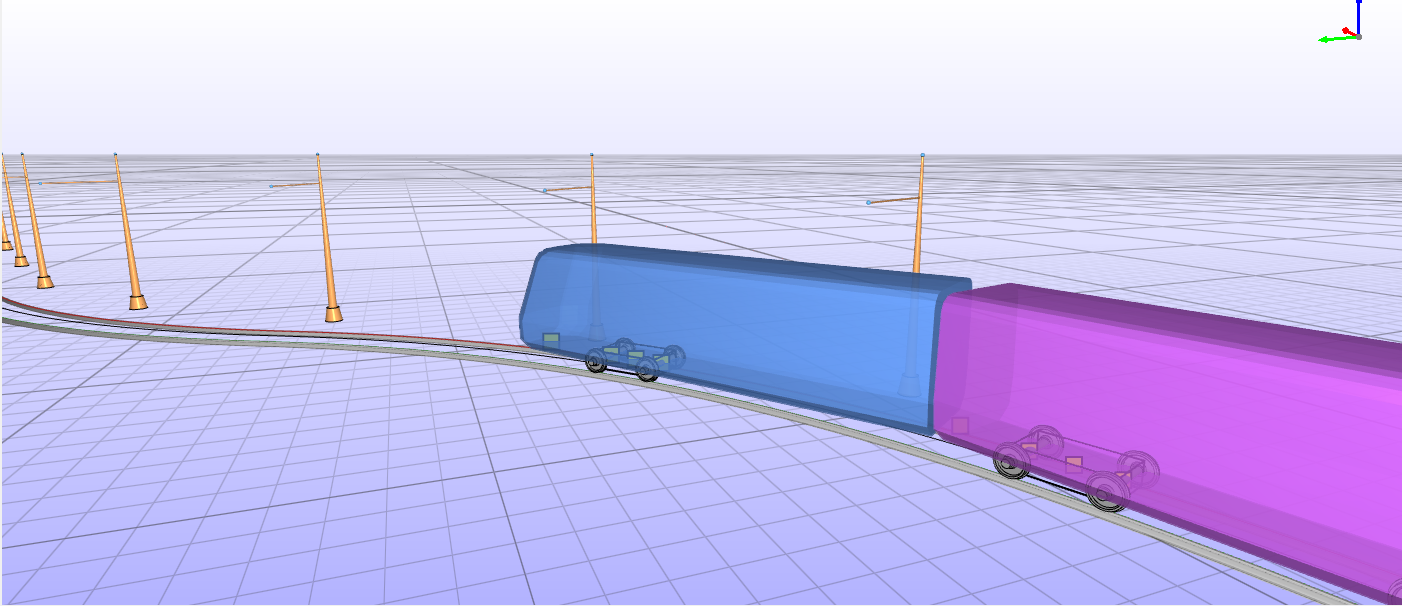
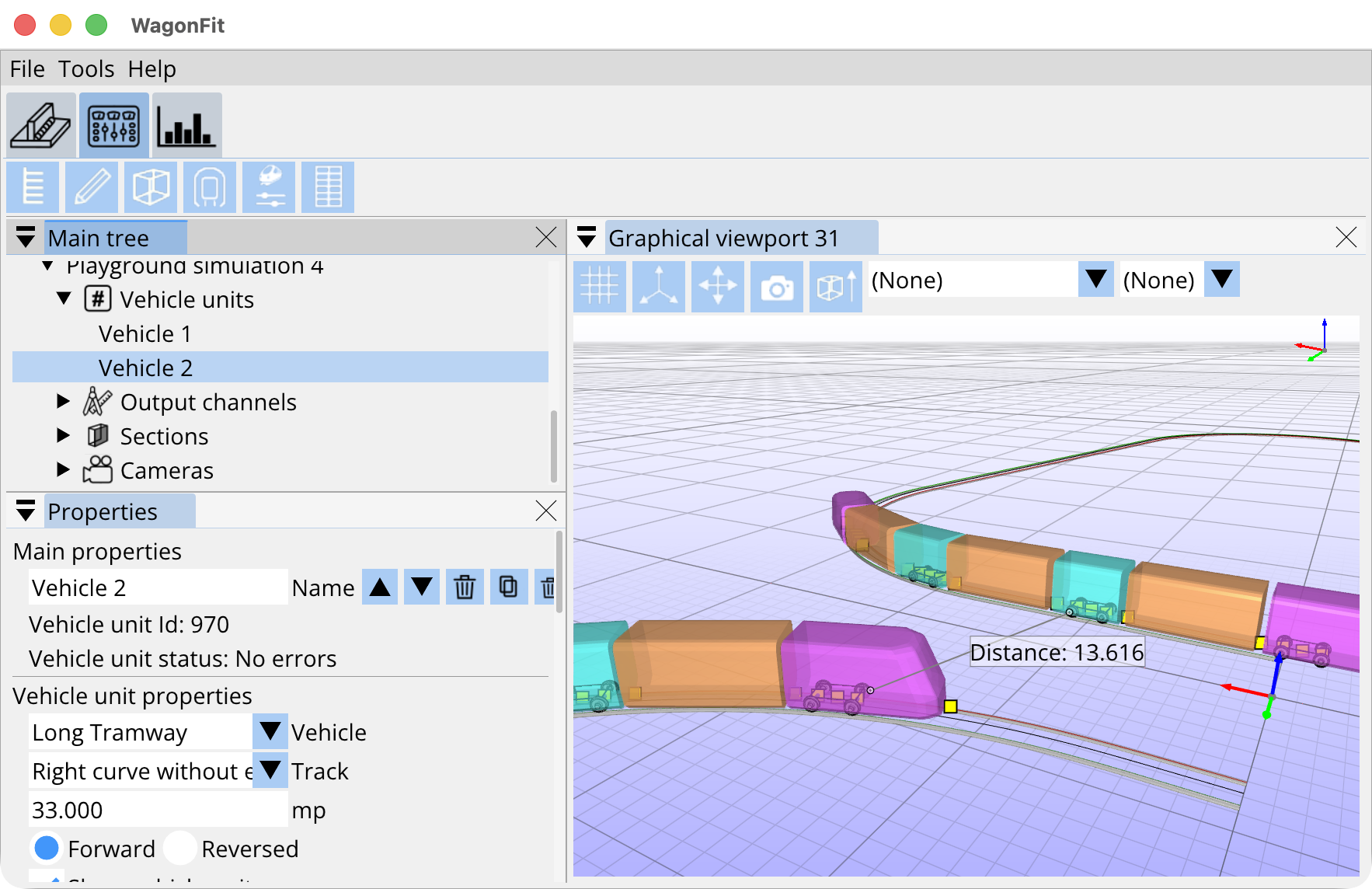
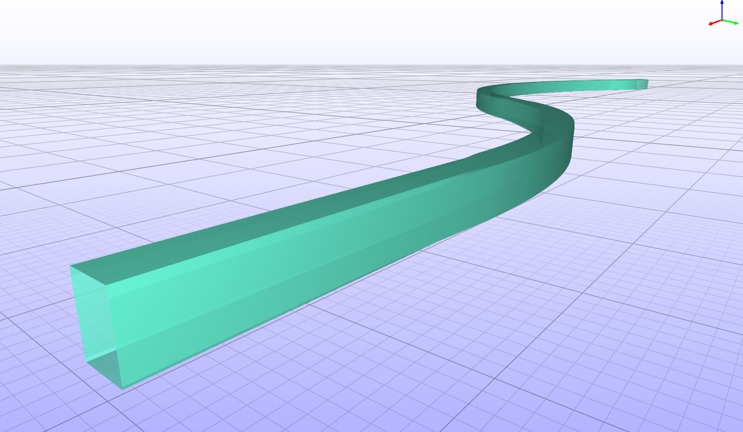
WagonFit simulates vehicle movement along tracks, performing detailed vehicle-to-vehicle and track-to-vehicle measurements throughout the process. This ensures a comprehensive analysis of spatial interactions and clearances, supporting optimal design and operational efficiency.
Vehicle and and track fill the space
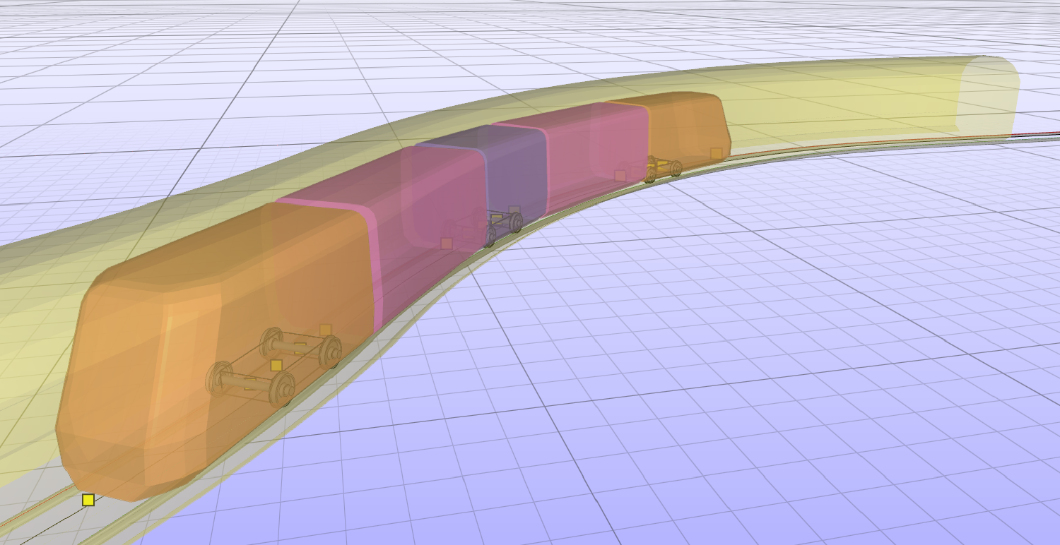
One of WagonFit’s key outputs is the precise calculation of a vehicle’s utilization within the track clearance envelope, offering detailed insights into how the vehicle interacts with the available space. In addition to this, the software determines the maximum allowable utilization for a vehicle to safely and efficiently fit within the track’s dimensions. These calculations are critical for ensuring compatibility between vehicles and tracks, optimizing design parameters, and preventing operational issues caused by inadequate clearances or space constraints.
Advanced Core Technology
At the heart of WagonFit is a real-time, fast-calculation kinematic solver. This innovative solver determines vehicle positions using only the necessary geometric and anatomical parameters, eliminating the complexity of incorporating stiffness, damping, and inertial parameters typically required in dynamic models.
True 3D Gauging
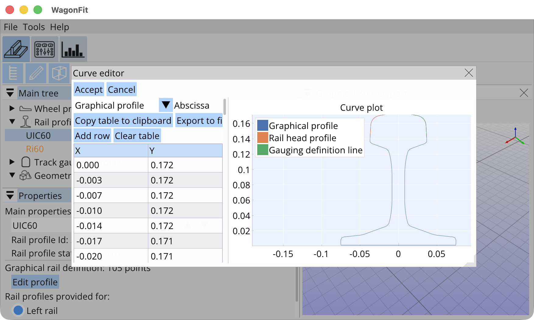
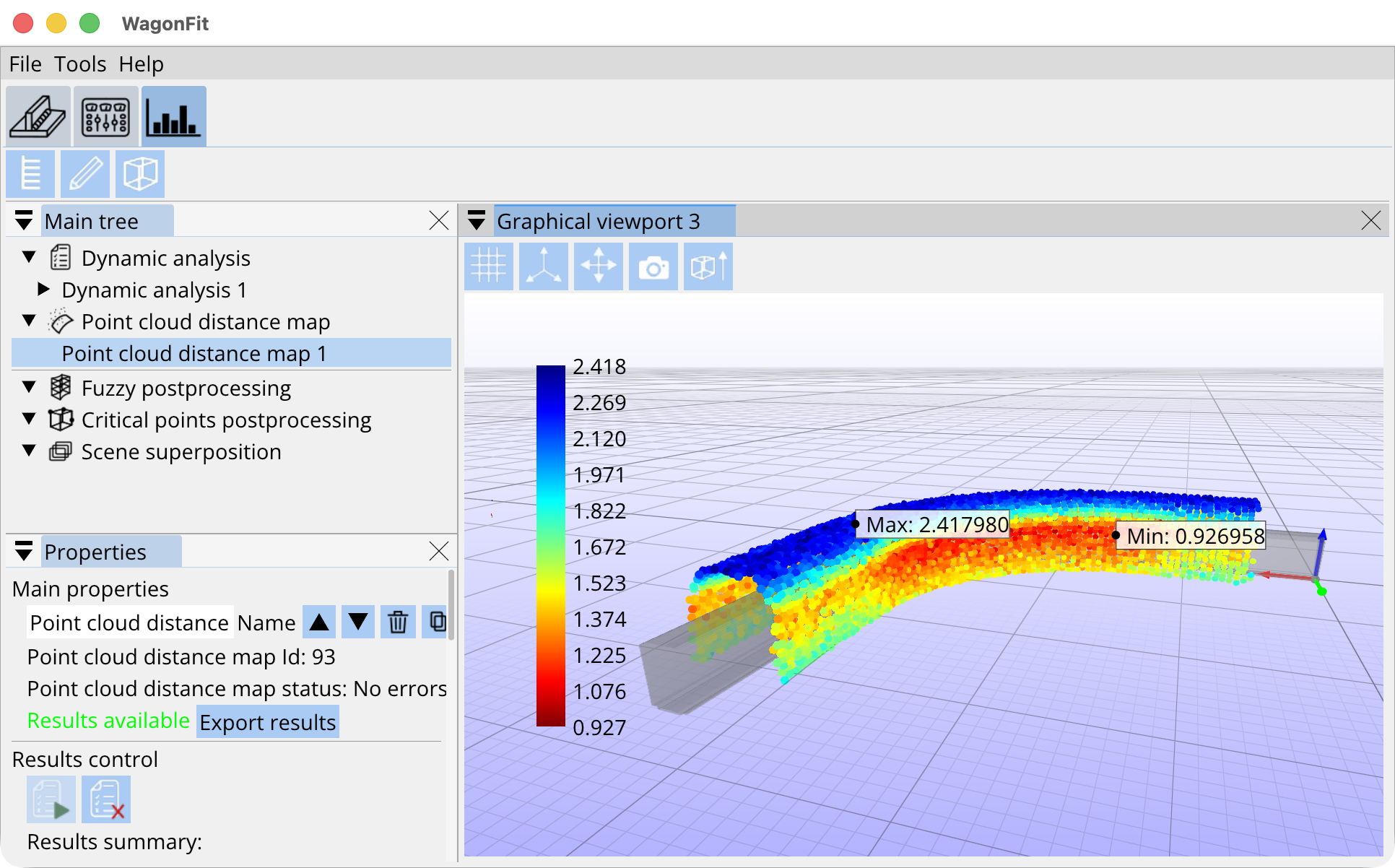
Effective gauging requires managing vehicle-track interactions within a spatial environment. WagonFit operates entirely in 3D space, capturing the complexities of moving vehicles within rail lines with unmatched accuracy. This process incorporates 3D elements, including LiDAR measurements, to deliver detailed spatial analysis and modeling.
Automatic sections analysis
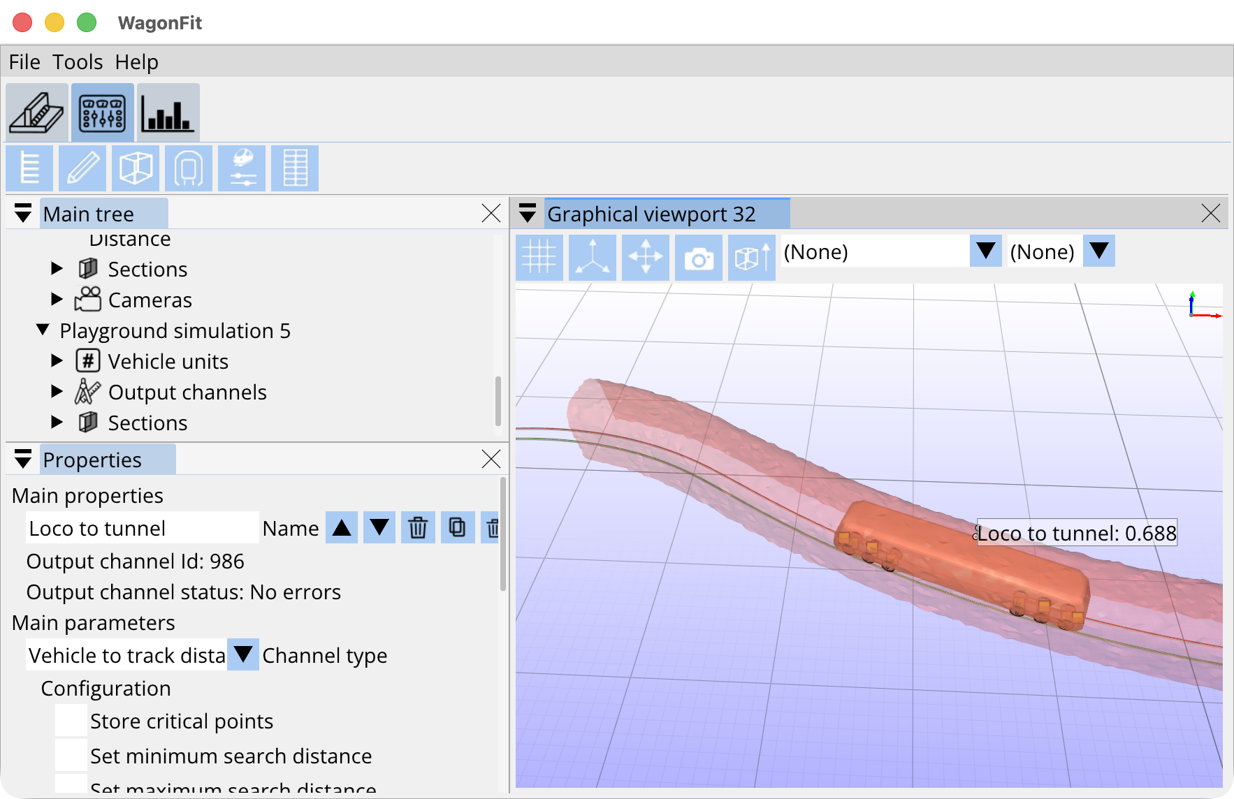
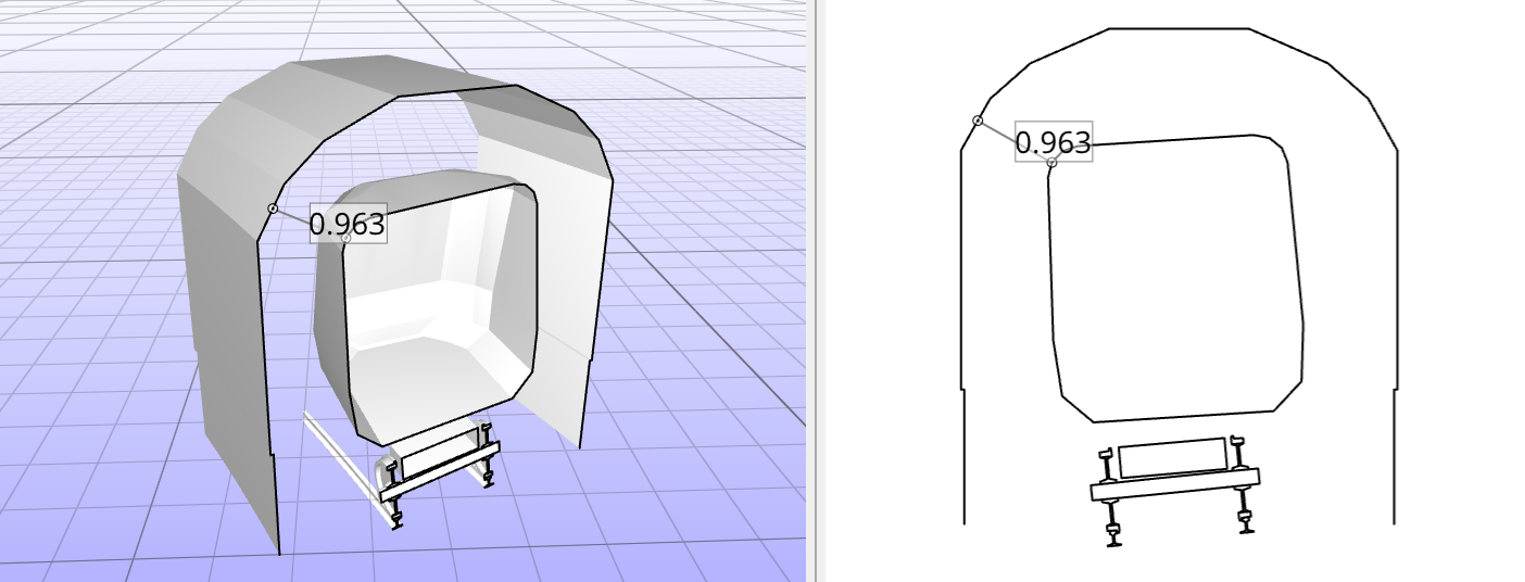
WagonFit automatically extracts cross-sections along the vehicle’s trajectory, enabling detailed clearance evaluation at every point of the route. Each section represents a precise cut through the 3D environment, displaying real-time distances between the vehicle’s envelope and the surrounding infrastructure. This process ensures complete coverage of the track, identifies potential infringements, and provides engineers with an intuitive visualization of spatial relationships within complex geometries.
Support for Arbitrary Multi-Articulated Layouts
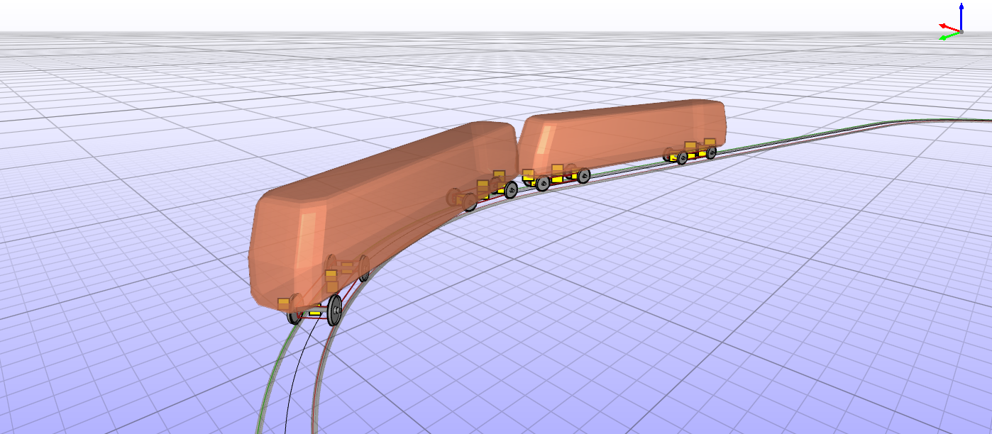
WagonFit supports any type of articulated vehicle configuration. Users can easily construct vehicles by assembling the required components and connecting them with appropriate joints, ensuring maximum flexibility.
Industry-Standard Interoperability
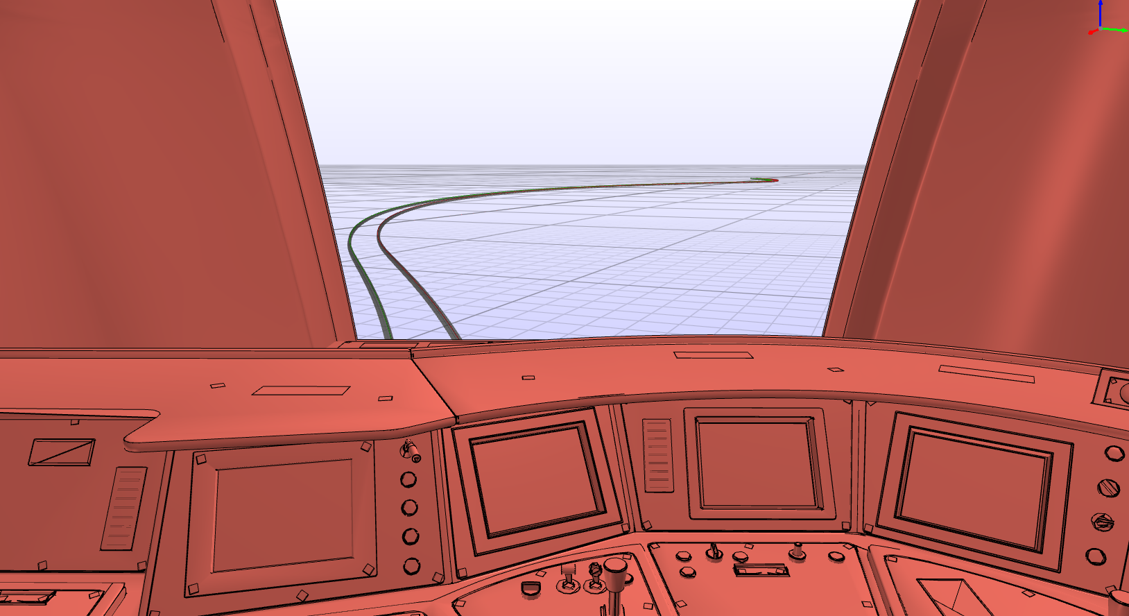
Multiple industry-standard file formats are supported, ensuring seamless integration with external CAD tools and facilitating smooth information exchange. Users can perform precise measurements using actual geometries or gain an immersive perspective from within the vehicles.
High-Speed Batch Processing
WagonFit’s high-speed solver enables thousands of batch calculations to be performed in a reasonable time frame, ensuring reliable results without the need for simplifications. This capability allows users to identify the most optimal geometries efficiently.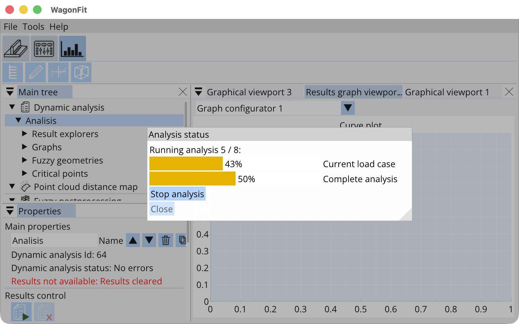
Holistic Gauging Analysis
Gauging is a dynamic interaction between vehicles and trackside infrastructure. Unlike traditional programs that focus solely on vehicles, WagonFit treats gauging as a two-part system. By analyzing both vehicles and infrastructure equally, it ensures a comprehensive understanding and optimized outcomes.